Design and Build a Real Life Power System Model

Introduction

It is important for an Electrical Engineering undergraduate to know about power systems in theoretical as well as in a practical approach. Thus, a power system simulator is ideal to understand practically the theories learnt in class. Commercially available models though are in existent, the endeavor was taken to design and build a power system simulator, as a final year project. The simulator is a scaled down model of the actual power system prevailing in the Sri Lankan context. Though it is a scaled down model, all electrical components such as generators, relays, circuit breaker panels are all actual industry used components. As a continuing project many aspects are being developed piece by piece under the guidance of the supervisors and with financial support from the industry. This project provides the basis for the fulfillment of the aspiration by the Department of Electrical Engineering, University of Moratuwa, to give a firsthand experience for the undergraduates before they encounter industrial training.

Project Scope

Figure 1: Power System Model
When completed the model will consist of,
  •     A synchronous generator/transformer unit with voltage control   
  •     A prime mover (an induction motor) with governor control (VSD drive)
  •     Manual synchronizing facility with the grid (mains supply)
  •     4 Transmission lines, a grid substation and a distribution system
  •     Variable resistive and inductive loads
  •     An integrated protection system to detect and clear the faults
  •     Instrument transformers (Current Transformers and PotentialTransformers) to provide information    to the protective and metering systems
  •     Metering facilities at various points in the system
  •     Vacuum Circuit breaker Panels and Facilities for remote operation of circuit breakers.
  •     A fault creation facility for the application of faults on transmission lines
  •     Laboratory practical’s on power systems, fault clearance and protection schemes

Project Objectives for 2013 

This year embarks the 4th phase and the following objectives are initiated for the completion of the project.


Fault & Load flow study and current transformer specification

A thorough load flow analysis was done to understand the system in operation. A fault study was done to determine the fault currents in different instances. The nominal current and fault current was taken from the study. The relay burdens were found by the manuals and other official documents. The knee point voltage was then calculated. By the parameters it was concluded that current transformers with a ratio of 60/5 and burden of 7.5VA would be best for implementation as they were commercially available.

Implementation of donated mechanical and numerical relays

Several numerical and mechanical relays have been donated by numerous contributors and these are being appropriately implemented onto the circuit breaker panels in the power systems laboratory. Due to the diverse nature of the relays, they were studied individually and extensively, ultimately learning how to program and operate. The relays which were donated will simulate the following protection schemes.
  1. Transformer protection (Over current, Differential)   
  2. Line Protection (Differential, Distance, Overcurrent, Directional overcurrent)
  3. Generator protection ( Overvoltage, Negative sequence, Overcurrent, Differential)

Implementation of load

It was decided that for the start, a resistive load of 3.3kW would be implemented to complete the distribution segment of the power system model. Implementation of inductive loads will be facilitated in the expansion of the project in the future.

Laboratory practical’s

Currently laboratory practical’s are being designed to be tested among the undergraduates as a pilot project before establishing it in the curriculum.

Generous donations have been made by LTL Holdings (Pvt) Ltd, Ceylon Electricity Board, Balfour Beatty engineering services Ceylon (Private) Limited,Hayleys Industrial Solutions (Pvt) Ltd, ABB Sri Lanka, FDK Lanka (Pvt) Ltd and by Lanka Electricity Company (Pvt) Ltd.

Project Supervisors: Professor J.R.Lucas | Eng. J. Karunanayaka
2009/2010 Group members: G.B.Alahendra| A.C.P.Aluthgama| P.G.L.Arachchi | G.U. De Silva
2010/2011 Group members: S. V. Herath| K. S. Hettiarachchi| W. J. M. L. Himal |C. Ileperuma
2011/2012 Group members: T.G.R.Lalitha | K.D.S.Kuruppu | L.L.U.J.Lenaduwa|   D.R.Liyanage
2012/2013 Group members: A.R Devinda| D.M.S Dissanayaka| C.L Fernando | M.H.M Fernando


For further information please feel free to contact us by energyzee.projects@gmail.com

Development of a prototype of vehicle active suspension system

Introduction

The aim of the project is to develop an active suspension system for vehicles. In this project, the main objective is to suppress the vibrations caused due to the imperfections of the road surface and give a better stability to the sprung mass. In order to achieve this goal, the suspension system changes its characteristics and suppress the vibrations according to the vibration level of the road and applied disturbances.

Project scope

The proposed method consist of a controller, linear motor driver, linear motor acting as an actuator and feedback sensors are used to complete the control system. The controller will accumulate suppressed vibration performance details of the system and takes position feedback of the motor using a linear encoder and motor current feedback using a current sensor to provide desired output signals to the motor driver. The desired output is calculated using motor disturbance observer technique. The response of the suppressed vibration is transferred to controller using a 3D accelerometer and the controller save them for analysis.


Figure 1: Block Diagram

The control signal then transferred into the motor drive module which provides power to linear motor USING PULSE WIDTH MODULATION. The actual current if the linear motor is measured by a current sensor using shunt resistance current measurement method. Current sensor used in between driver and linear motor to calculate the exact current transferred to motor. This measured value then used in DOB to calculate load torque.  The Linear motor acts as the actuator of system, providing required dynamic suspension response to suppress vibration experienced by motor body itself. The linear motor is capable of delivering required torque and speed response directed by controller through motor driver.The Linear encoder measures the motor position and sends the position measurement to controller for system response measurement. These systems are connect as described above and as in above block diagram to provide a viable solution to our problems.

Conclusion

The effectiveness of the active suspension system with respect to prevailing passive suspension system can be observed by comparing the vibration suppression capability of the both systems in different vibration levels. The effective usage of the active suspension system can be implemented to improve the control, contact and comfort of the motor vehicles.

Project Supervisor: Dr.Harsha Abeykoon
Group members: P.A.M.M.B. Abeyrathna | W.A.S.P. Abeysiriwardane | S.W. Amarasinghe | W.M.S.L. Ariyasinghe

For further information please feel free to contact us by energyzee.projects@gmail.com

E-waste - A national issue to be considered...

Electronic waste (e –waste) is one of the major environmental issues which are currently faced by the developing countries as well as the developed countries all around the world. With the rapid technological development, many innovative products arrive to the market. The demand for those innovative products is growing day by day and those innovative products replace the existing ones. Thus, that will create a hazardous situation regarding the disposal. In our country – Sri Lanka too, the current consumption of the new technological equipment is increasing in a considerable rate with respect to the past and the disposal of waste will be a huge issue, in the near future. So, it’s very much convenient to be aware of e – waste, its impact and the e – waste management system in Sri Lanka.

E –waste …

Discarded electrical and electronic appliances such as computers, mobile phones, batteries, bulbs etc…, can be considered as e – waste.
These e – waste consist of various harmful substances such as Lead (Pb), Nickel (Ni), Antimony (Sb), Arsenic (As), Cadmium (Cd), Mercury (Hg) etc…  Therefore, many environmental and health impacts can be occurred with the e – waste.

The main environmental issues associated with the e – waste are, most of the waste is not decayed, addition of harmful substances to the soil and emission of harmful gasses to the atmosphere because of the burning of the waste. The most common health hazards engaged with the e – waste can be described as follows.


How can we minimize e – waste?

In order to overcome the problem of e-waste, there exist several possible approaches as follows.
•    Use only the essential electrical and electronic equipment.
•    Get the maximum use of the equipment, throughout its entire life-time.
•    Forbid the transfer of used electronic and electrical equipment from developed countries.
•    Recycle the waste which is not suitable for usage.

If the consumers such as domestic, commercial etc use only the most essential electrical and electronic equipment, the contribution towards reduction of e-waste is enhanced. On the other hand, by getting the maximum use of equipment throughout its entire life time, consumers will not switch to the new equipment immediately. This fact will also be helpful to minimize e-waste. Most of the developed countries export their own e-waste to the developing countries for a cheaper price in order to get rid of those. Because of this action many developing countries have faced a huge problem in disposing e-waste. Therefore forbidding the transfer of used equipment is a must.

Recycling is the main step of reducing the impact of e-waste. In the process of recycling, the waste is sent for the extraction of substances. And those extracted substances can be used in manufacturing processes which contribute towards saving natural resources. Therefore recycling will reduce the air pollution, water pollution and emission of greenhouse gases.

Approach to waste management in Sri Lanka…

Sri Lankan government has already established the acts for e-waste management under the Central Environmental Authority (CEA). There are some companies who have engaged in e-waste collection and recycling under the inspection of CEA.

Though there exists an e-waste management concept in Sri Lanka, most of the people are not aware about that, as it is only limited to the Colombo city area. But as a result of technological development the usage of electrical and electronic equipment has spread all over the country. Therefore it is very much essential to implement a national level waste management program.

When considering the current situation, it is very much clear that people don’t have a proper knowledge on the harmfulness of e-waste. The foremost action of this e-waste management is to make people aware regarding this matter and impact on their lives. Then as an approach, establishment of waste collection centers in each area is a must. Also recovering and recycling material by safe methods are essential. If we can conduct such a national level e-waste management program from today itself, we will be able to win the battle of e-waste disposing which will appear in the near future.

Article By:  Harshani Bendarage
                  Tharangi Gunarathna

What is so special about Inverter type Air Conditioners….


Have you ever tried hiding the remote controller of the air conditioner simply to get rid of the extensive current bill? If so, inverter type air conditioners are just the thing for you!

This particular strategy of energy saving is suggested in a popular TV advertisement, nowadays. As it suggests, with this inverter type air conditioners energy saving up to 60% can be expected.  Therefore, it is worth to have a look, how this new phase of technology accounts for the energy efficiency and the performance of the air conditioners.

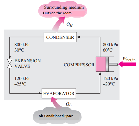
The basic operation of the air conditioners is to extract the heat energy from a compartment area and release it to the outer environment.Therefore, when maintaining the air conditioned space, at a lower temperature, air conditioner has to extract heat energy from a lower temperature medium, and release it to a higher temperature medium. From the second law of thermodynamics (Clausius statement), for this to happen, there should be some external work done somewhere in the cycle. The work needed for this thermodynamic cycle is done by the compressor of the air conditioner.

Operation principle schematic
Thermodynamic cycle in Air conditioners

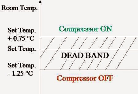
The point of the cycle, where air conditioning can be easily controlled, is the compressor motor.  In conventional air conditioners, on off control of compressor is used to maintain the temperature of the air conditioned space around the set value. That is, if the temperature of the room is below the ‘set value-some tolerance’, compressor will completely turn off, whereas if the room temperature rises above the ‘set value + some tolerance’, compressor will completely turn on. A dead band is there to avoid rapid fluctuations of the response around the set point, which would occur otherwise.

On- Off control operation

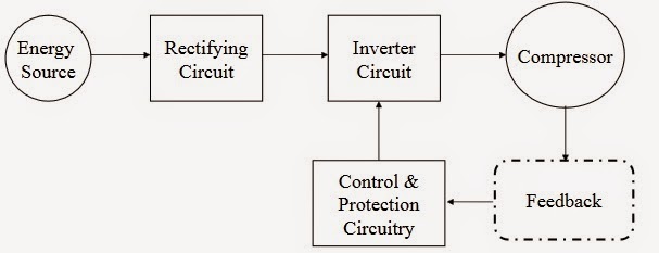
In inverter type air conditioners, in contrast, the conventional on- off type control is replaced with a wide range of speed control technology. That is, with this new technology, the speed controlling of the compressor is possible rather than just turning on and off. To control the speed of the compressor motor (which is an induction motor), over a wide range, a variable frequency motor drive is used.

Control block diagram of the compressor

Operation block diagram of the inverter

At stating of the air conditioner powerful cooling is required to reach the set temperature.When the set temperature is reached,only a little power is sufficient to maintain the achieved temperature when it comes to inverter type air conditioners. This is achieved by controlling the compressor speed. In contrast, with conventional air conditioners, only the on-off control of high the speed compressor is possible.That in turn results in large fluctuations of temperature.Subsequently this leads to a wasteful consumption of energy.

How much of this wasted energy you can save by replacing the old air conditioner with an inverter type one mainly depends on the factors such as, environmental conditions, thermal insulation of the compartment area, set temperature, rate of change of the room conditions, etc. 

Another major plus point with inverter type air conditioners, over the conventional type is its ability to reach the set temperature smoothly and quickly. And also it is capable of maintaining the air conditioned space around the set temperature with a lower tolerance. Due to more precise temperature control, enhanced room comfort can be expected. 

With the conventional type air conditioners, sharp fluctuations of voltage which would disturb the other electricity consumers and appliances could occur due to frequent on/off of the compressor. But with inverter type air conditioners, that issue is completely eliminated.

Anyway, with the added complexity due to the introduction of power electronics, production cost tends to increase proportionately. Moreover repairing and troubleshooting of this new inverter, is neither simple nor easy as it is with the conventional one.

Whether you like it or not, conventional air conditioners are now being rapidly replaced by this newly introduced member!

References:

Article By: Thisandu Kahingala 

Pumped Storage: A battery with a promising potential

Even though most people are familiar with the basics of conventional hydro, pumped storage is still a quite unfamiliar concept which provides solutions to some of the vital problems faced in the general power systems. One of the important usages of pumped storage comes in to play in matching constantly-changing supply from power producers with constantly-changing demand of power consumers by acting as a facility that can supply extra power when demand increases by taking in extra power when supply stays high while demand drops. Other than that, it is also considered as the largest capacity form of grid energy storage available, providing a large scale energy storage option for intermittent power sources. These points would be discussed extensively later in the article as it is important to first identify what pumped storage is exactly.
  
What is pumped hydroelectric storage?

A pumped hydroelectric storage facility typically consists of pumps/generators connecting an upper elevation reservoir and a lower elevation reservoir (As shown in Figure 1).

Figure 1: Basic overview of a pumped hydroelectric storage facility (Extracted from http://www.bbc.co.uk/bitesize/standard/physics/energy_matters/generation_of_electricity/revision/3/)

This method stores energy in the form of potential energy of water, pumped from the lower elevation reservoir to the higher elevation reservoir. The pumps utilize relatively low-cost electricity from the grid during off-peak hours to move water from the lower reservoir to the upper reservoir to store energy. During periods of high electricity demand (peak-hours), the stored water is released through turbines to produce electric power.

Pumped storage as a load balancing tool:

This specific function could be efficiently portrayed through the Sri Lankan power system, where the daily electricity demand fluctuates significantly and the late evening peak demand (around 2000 MW) is more than double the off-peak demand (around 800 MW). This situation leads to the requirement of developing generation facilities to serve the peak demand specifically.  (Sri Lankan daily load curve (in general) is shown in Figure 2)

Figure 2: Sri Lankan Electricity demand load curve (Extracted from
http://www.nalakagunawardene.com/tag/power-load-curve/)

Currently this high peak demand is satisfied through diesel/heavy fuel fired thermal plants (if the hydro generation capacity is not enough) which leads to a higher generation cost per unit whereas during off peak, plants with lower generation costs (e.g. coal fired power plants) are part loaded due to low demand making them inefficient (under-utilized).

This imbalance points us to the function of a pumped storage as a load balancing tool where during off peak, the pumps could utilize low cost energy by full loading the coal fired power plants and during the peak, the stored water could be used to satisfy the high demand presenting an economically advantageous situation than the normal conditions.

Even though pumped storage might be a novel concept in the Sri Lankan context, it has been utilized effectively in many countries over the world for this specific function.

Pumped storage as a battery for renewable energy:

It is known fact that one of the main drawbacks of electricity generation using renewable energy sources like wind, solar etc. is the high amount of intermittency present and the lack of suitable energy storage system which compensates to this intermittency.

Pumped storage is considered as a possible solution to this issue as it provides an energy storage opportunity, as potential energy in water in larger capacities. Already pumped storage systems are built on research basis which use wind turbines or solar power to drive water pumps directly, thus providing a more efficient system to smooth out the variability of energy captured from the wind or sun. (Example: Ringwall- storage-hybrid power plant in Germany)

Prospects for future:

Even though there are many new research concepts and novel ideas popping out regularly regarding  pumped storage technology, few stands out among those as really bright prospects for the future. One of them is utilizing sea-water for a pumped storage plant which Japan has already pioneered. The Okinawa seawater PHS station, which has commenced operation in 1999, is the world’s first seawater pumped storage facility.

Also researchers had proposed the possibility of utilizing an underground cavern as the lower reservoir for a pumped storage project. Recent examples include the proposed Summit project in Norton, Ohio, the proposed Maysville project in Kentucky (underground limestone mine), and the Mount Hope project in New Jersey, which have used a former iron mine as the lower reservoir.

Where Sri Lanka stands regarding this technology:

Sri Lanka as a country primarily based on hydro resources to generate power, should possess the suitable terrains with significant elevation difference between the two reservoirs and significant amount of water resource. Studies have already been conducted in this regard and several possible sites have been identified for a pumped storage facility. One of the main candidate sites is “Kiriketi” which is based on Kiriketi Oya- North of Samanalawewa Reservoir. More details about these studies could be found in the original research paper “PLANNING OF PUMPED STORAGE POWER PLANTS IN SRI LANKA” by MTAP Wickramarathna published in SLEMA Journal,Vol 14,No.2, September 2011.
(http://www.slema.org.lk/news_events/SLEMA-Journal/SLEMA-Journal-Sept-2011.pdf)

It could be concluded that, in the Sri Lankan context, a pumped storage facility could be a valuable addition to the power system as it provides a platform to operate the system more economically by utilizing the low cost coal power plants coming up and an opportunity to integrate more renewable energy sources to the system.

References:

http://thinkprogress.org/climate/2013/08/27/2524501/hydro-pumped-storage-climate-change/
http://www.renewableenergyworld.com/rea/blog/post/2013/11/pumped-storage-in-the-spotlight
http://en.wikipedia.org/wiki/Pumped-storage_hydroelectricity

Article By: Asith Kaushalya and Chathuranga Fernando

Evaluating the public perception on domestic electricity tariff structure | Survey


Go to survey (English version)
Go to survey (Sinhala version)

1. Purpose of the Survey

The EESoc panel discussion was initiated with the purpose of serving the power sector with an unbiased and a fruitful discussion regarding a timely issue. Considering the prime importance prevailing in the national power sector, the theme for the year 2013 is suggested as “Towards a rational consumer tariff”. The panel will provide suggestions on how Sri Lanka can move into a more rational tariff structure.

As we believe, the suggestion would definitely be a technically sound and feasible one considering all the engineering and economic aspects in the field. This survey is proposed with intention of integrating social aspects to this proposal to be suggested.

Whatever the suggestions, acceptance of this ultimately depends on the consumer perceptions and their impression on this change. Requirement of a change management programme is a highly essential and important aspect especially in Sri Lankan context. This can be achieved by conducting an effective communication between supply side and consumers, providing accurate information to consumers.

Before moving to a change management program, it is necessary to understand their interest, knowledge, behaviors, beliefs and attitudes towards the electricity pricing. EESoc is expecting to proceed this survey with the intention of all of above mentioned purposes, in collaboration with the EnergyzEE team.

2. Objectives of the Survey

  • Prepare the sample to represent the actual population based on the consumption of units.
  • Educate people on the different tariff structures and get a feedback (comments) on the tariff structures according to their personal views.
  • Get the public perception on the relationship between electricity cost and electricity tariff.
  • Evaluate the understanding of the public about the load profile in conjunction with electricity tariffs.
  • Evaluate according to the public perspective what communication channels are best suited to convey information about tariff and how those media could be effectively utilized

Introduction to Wind Power Plant technologies in the world


Renewable energy is the main concern of the global energy sector to face the energy crisis occurred with the depletion of fossil fuel. Wind energy is one of the prominent renewable sources of energy currently used globally. Following the global trend, Sri Lanka too has wind power plants connected to the national grid that consist of three main types of generators which are variable speed synchronous wind generators, doubly-fed induction wind generators and fixed speed asynchronous wind generators (FSAWD). This article talks about the main construction modes of each type of wind power plant available globally.

Fixed speed asynchronous wind generator

These types of generators are operated with less than 1% variation of rotor speed, which is also the reason to be called as fixed speed wind generators. They are equipped with a squirrel cage induction machine which is directly connected to the power grid (Figure 1). The speed of the rotor is determined by the frequency of the network not from the wind speed. It is done with the speed multiplier ratio and by the generator type. In order to increase the power production, most of the wind generators use two coils for low wind speed and high wind speed. There are 8 poles and 4-6 poles available respectively for each type of coils. These generators have used soft starters as for starting up of the generators since starting current is very high and it might also be a cause for voltage variation in weak power system network.

Mainly there are two types of fixed speed wind turbines available in the industry as pitch control and stall control. In pitch control type turbines, blades are not fixed to the hub so it can be rotated a few degrees to fully confront the wind in order to produce full power or be in line with wind direction to extract no power. In stall control type turbine blades are fixed to the hub rigidly and they are designed in a way that the airflow over the blades is a laminar air flow to turbulence flow at high speed.  But the drawback is, rigidly fixed blades limit the mechanical power extracted from the wind at high speed to protect the machines from overloading.


Wound rotor induction generator

Wound rotor induction generators use variable rotor resistance control in order to achieve output power control. These types of wind turbines can extract wind power in a optimum way, compared to squirrel cage induction wind generators so they are generally employed with variable speed wind turbines. They are stall controlled wind turbines (blades are rigidly fixed to the hub) to focus on the rotor resistance control.

Main objective of the rotor resistance controller is to obtain the operating point with maximum possible wind power extraction without exceeding machine limits. Wound rotor induction wind generator is illustrated in figure 2.


Variable speed doubly fed induction wind generator

Due to high energy efficiency and controllability, variable speed doubly fed induction wind generator has become more popular these days. This model is called doubly fed induction generator because the grid is powered by two feedings, shown in Figure 3, as one from the stator, which is connected to the grid directly while other is from the rotor connected to the grid via an AC/DC/AC converter. Converter of this turbine handles only 30% to 40% of the generator output.

Ability to change of rotor voltage allows control of operating conditions of the generator as in low speed drop in rotor speed direct the generator into a sub synchronous operating mode by absorbing power from the grid and also during high wind speed, the DFIG wind turbine operate at super synchronous speed delivering power originated from the rotor through the converters to the power system. Ultimately rotating speed of the DFIG rotor determines if the power is delivered to the power system via the stator only or via the stator and rotor.


Full power converter wind turbine generators

The ability of effectively decoupling the generator from the grid, improved fault response, operating at wide speed range has led to improve the popularity of full power converter wind turbine generators in the industry. There is a converter connected to the turbine as shown in Figure 4, to handle the entire output of the generator.

Introducing the new technology, full converter wind turbines are equipped with a permanent magnet alternator. This type of wind turbines with permanent magnet generators (PMGs) are excited by permanent magnets and it can also be excited by generator-side converters. These PMGs are normally connected to the grid via frequency converters. This makes a DC link from the power grid to the generator, as shown in Figure 4 and there is no any reactive power exchange between generator and power grid. As such the power factor of the wind power plant output is 1. The AC-DC converter is a diode-bridge rectifier and a buck-boost converter which controls the DC link voltage.
Reference:
O S D De Silva, H K C O Dayarathne, V I P Dasanayake, J G D S De Silva and A S Rodrigo; Wind Generator Dynamics: Modelling of Fixed Speed Asynchronous Wind Generator using PSS/E
ISSN: 2545-9557

Article By: Team SOID